OpenWiFi Documentation
Contents
- Use Case
- PHY Selection
- PHY Specs
- Architecture & the XPU
- Packet Injection
- Operating the PHY
- Bare-metal
- Linux
- RF Front End
- Compile-Time Parameters
- Runtime Configuration
- ADC / DAC Paths
- RF Chip Specs
- WFB-ng
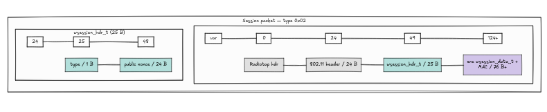
- Session Packets
- Data Packets
- Patched WFB-ng (TODO)
- Use Case: Throughput & Latency
- WFB-ng Overhead
- Producing the Same Project Again
- Board Characteristics (TODO)
- Choosing a WiFi Dongle
- Building and Running wfb-ng
- Transmitter Setup (AntSDR)
- Receiver Setup
Use Case
- Full HD Video
- Long Range Transmission
- Bidirectional Communication
PHY Selection
To choose our PHY, we need to look at three things: - Specs - Architecture - RF chip
PHY Specs
We have 802.11a/g/n — max of WiFi 4 features to work with. The specs of our PHY are the typical WiFi PHY specs you'd find in the 802.11 standard:
- FFT/IFFT size of 64
- Modulation:
- BPSK
- QPSK
- QAM16
- QAM64
- Short and long guard interval (CP of 8 and 16 samples)
- Convolutional encoder
- FCS checksum
- No LDPC
- No STBC (MIMO is supported — CDD will be discussed in the RF chip section)
Architecture & the XPU
Now, WiFi isn't exactly famous for long range — yelling at your brother because he unplugged the WiFi signal extender is proof enough of that. So how on earth are we using WiFi for drones? The answer is simple: we first need to understand why WiFi can't reach long ranges in the first place, and for that we need to look at the architecture:
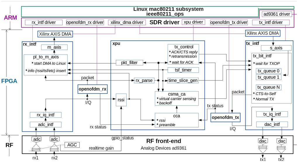
The whole idea centers on the unit in the middle, the XPU (eXtended Processing Unit), which acts as a MAC layer controller. The reason it's implemented in hardware is the same reason WiFi struggles at long range: in the WiFi standard, the flow is that anyone who wants to send first senses the channel to check it's available, and once it's clear to send, the TX sends a message to the RX — the RX must then send an acknowledgment that it received the packet within 16 microseconds, which over long range isn't achievable. The XPU handles this by doing the following:
1. CSMA/CA channel access - CCA (Clear Channel Assessment) — monitors RSSI against a configurable threshold to sense whether the channel is idle or busy. - DIFS / EIFS / SIFS timing — enforces the mandatory inter-frame spacing before transmission. - NAV (Network Allocation Vector) — virtual carrier sensing; reads the duration field from received frames and defers transmission accordingly, avoiding hidden-node collisions. - Random backoff / contention window — manages CW min/max per queue and random slot backoff.
2. ACK handling - Auto ACK — the TX automatically sends an ACK frame exactly one SIFS (16 microseconds) after the unit receives a packet. - Sender waiting for ACK — the sender waits for an ACK after sending a packet to the receiver.
The XPU also handles a bunch of other, less exciting things that we bypass entirely — more on that in the "Operating the PHY" section.
Packet Injection
Suppose you have hardware you have full access to. Here's how it works: the tx_intf from the architecture above communicates with the XPU, and once it gets the clear to send, it signals the PHY to start via the phy_tx_start signal. The openofdm_tx block then starts consuming the contents of its assigned BRAM — a 64x1024 BRAM that holds exactly one packet.
As you can see, tx_intf has N queues — in our case, 3 queues split across text, audio, and video for priority handling. None of this is needed for our use case, since we only use the video queue.
For packet injection, we have two scenarios:
1. Bare-metal: simple — in bare-metal you just write to a couple of registers (refer to "Operating the PHY" below) to disable CCA and ACK, then use your own custom driver — one that skips all XPU logic entirely — to start transmitting and control the tx_intf registers directly (again, see "Operating the PHY" for details).
2. Linux: unfortunately, life isn't quite as simple here. When you build hardware that follows a given standard and want it to be plug-and-play, you need to comply with Linux's implementation of that standard. For example, if you buy a WiFi module like the BL-M8812EU2 and want to use packet injection, here's the flow: Linux has its own 802.11 implementation, and it provides a kernel interface that your WiFi dongle connects to (see the packet(7) man page). You open a socket to the hardware dongle, and that socket moves bytes from the hardware driver up to you — from there, you can do whatever you want with them. This is a simplified explanation; for the actual flow, look at the wfb-ng code (see the WFB-ng section for more details).
Operating the PHY
Now that we have the PHY, what do we do with it?
Bare-metal
Refer to the openwifi-hw GitHub repo to see how to compile the project against the AntSDR E200.
Linux
-
Download the openwifi image, unzip it, and burn it onto an SD card (≥16GB). Afterwards, the SD card should have two partitions:
BOOTandrootfs. To flash the SD card, you can use an SD card tool (such as Startup Disk Creator on Ubuntu) or theddcommand:```bash sudo dd bs=512 count=31116288 if=openwifi-xyz.img of=/dev/your_sdcard_dev
To get the correct count value, check the .img file first: fdisk -l img_filename
```
-
Configure the correct files in the
BOOTpartition for your board:- Copy the files in
BOOT/openwifi/board_nameto the base directory of theBOOTpartition. - Delete the
rootfs/root/kernel_modulesdirectory (if it exists). - Delete the
rootfs/etc/network/interfaces.newfile (if it exists).
- Copy the files in
-
Insert the SD card into the board. Set the board to SD-boot mode. Connect the antennas. Power it on.
-
Log in to the board from your PC (your PC's Ethernet should have IP
192.168.10.1) with the passwordopenwifi:bash ssh root@192.168.10.122
If you have trouble with the serial connection, run:
sudo apt remove brltty
and the board should show up at /dev/ttyUSB0.
If you're setting up openwifi on the AntSDR for the first time, run:
./openwifi/setup_once.sh # reboot the board afterwards — only needed once, for a new board
Otherwise, just run:
cd openwifi
./wgd.sh
This script is the holy grail script — it does the following:
- Loads prerequisite kernel modules:
bash sudo insmod xilinx_dma.ko sudo modprobe mac80211 - Kills conflicting processes and tears down the old interface:
bash killall hostapd sudo service dhcpcd stop killall dhcpd killall wpa_supplicant sudo ifconfig sdr0 down sudo rmmod sdr - Reloads the FPGA bitstream. This is very useful if the Viterbi decoder stopped working (relevant for a two-AntSDR setup — not important if you're using a WiFi dongle), since the code runs on a Viterbi eval license with a counter baked into the bitstream that hits zero two hours after flashing.
- Initializes the RF front end.
- Loads all openwifi kernel modules in order:
MODULE_ALL = "tx_intf rx_intf openOFDM_tx openofdm_rx xpu sdr" - Configures the AGC:
bash
   ./agc_settings
For more on initializing the RF front end, see the RF Front End section.
After running wgd.sh:
./monitor sdr0 channel
(To find out which channels the PHY uses, see the iw dev section.)
That script does the following:
sudo ip link set sdr0 down
sudo iwconfig sdr0 mode monitor
sudo ip link set sdr0 up
sudo iwconfig sdr0 set channel channel_id
and then reapplies the AGC settings:
./agc_settings.sh
Next, we disable CCA — though "disable" isn't quite accurate. CCA works on a listen-before-talk (LBT) mantra: it senses the channel against a threshold, stored in register 8 of the XPU (XPU_REG_LBT_TH). We set that threshold to something absurd, like 355 dBm — a power level you'd only hit with a microwave gun strong enough to disturb your soul, which is also impossible — so the XPU always senses the channel as idle.
The command:
./sdrctl dev sdr0 set reg xpu 8 1000
# or
./set_lbt_th.sh 1
The difference: the first command sets the rssi_half_db value directly, and the second sets the dBm magnitude — different representations, same effect.
Then disable the automatic ACK on TX and the wait-for-ACK on RX:
./sdrctl dev sdr0 set reg xpu 11 48
RF Front End
For evaluating our RF specs, we use the AD9361 — a very powerful chip with a ton of knobs. This section covers the RF front-end configuration that openwifi uses.
Analog Devices provides its own custom Linux distribution, named Kuiper, which bundles all the kernel modules, drivers, and everything else needed for this hardware.
Compile-Time Parameters (system.bd)
ADC_DATAFORMAT_DISABLE   0
ADC_DATAPATH_DISABLE     0
ADC_DCFILTER_DISABLE     0
ADC_INIT_DELAY
ADC_IQCORRECTION_DISABLE 0
ADC_USERREPORTS_DISABLE  0
CMOS_OR_LVDS_N           0
DAC_DDS_DISABLE          1
DAC_IODELAY_ENABLE
DAC_IQCORRECTION_DISABLE 0
DAC_USERREPORTS_DISABLE  0
MIMO_ENABLE              1
MODE_1R1T                0
TDD_DISABLE              0
Runtime Configuration
- RX baseband gain — the digital gain we can set to give the samples more amplitude.
- The RF chip is controlled via SPI.
ADI provides HDL code in the fabric for chip communication:
axi_ad9361— the core IP, responsible for:- LVDS physical layer: framing and deframing of the 6-lane LVDS data bus.
- ADC datapath: IDELAY-based capture (the
ADC_INIT_DELAYparameter mentioned above), DC offset filter, IQ imbalance correction, data format conversion. util_ad9361_tdd_sync— a TDD (time-division duplex) synchronization utility. It generates a periodic sync pulse with a configurable period; not used in our project.util_ad9361_divclk— a clock divider utility. The AD9361 outputs a data clock over LVDS; this IP divides it down to generate the internal FPGA processing clock used by the ADC/DAC datapaths.util_ad9361_adc_fifo— a write FIFO on the ADC path. Bridges the clock domain between the AD9361 data clock and the FPGA fabric clock.util_ad9361_dac_fifo— a read FIFO on the DAC path. Symmetric to the ADC FIFO, buffering IQ samples before they're sent to the chip.
ADC / DAC Paths
ADC path (RX side):
LVDS → ISERDESE2 → format conversion (raw to 2's complement) → DC filter → IQ correction → user ports → rx_intf
DAC path (TX side):
tx_intf → user ports → [DAC datapath: IQ correction → DDS (optional, and as noted, disabled) → OSERDESE2 → LVDS pins]
The AD9361 has a neat feature: a built-in Direct Digital Synthesizer (DDS), a test tone generator for RF chip testing purposes. For a cool demonstration of what synthesizers look like at a much larger scale, check out this video.
RF Chip Specs
- RF 2×2 transceiver with integrated 12-bit DACs and ADCs
- TX band: 47 MHz to 6.0 GHz
- RX band: 70 MHz to 6.0 GHz
- Supports TDD and FDD operation
- Tunable channel bandwidth: <200 kHz to 56 MHz
- Dual receivers: 6 differential inputs
- Superior receiver sensitivity: noise figure of 2 dB at 800 MHz LO
- RX gain control
- Real-time monitor and control signals for manual gain
- Independent automatic gain control
- Dual transmitters: 4 differential outputs
- Highly linear broadband transmitter:
- TX EVM: ≤ −40 dB
- TX noise: ≤ −157 dBm/Hz noise floor
- TX monitor: ≥ 66 dB dynamic range with 1 dB accuracy
- Integrated fractional-N synthesizers
- 2.4 Hz maximum local oscillator (LO) step size
- Multichip synchronization
- CMOS/LVDS digital interface
WFB-ng
We've covered packet injection — wfb-ng builds on top of it, using Linux's packet injection implementation to build a reliable link.
wfb-ng is split into wfb_tx and wfb_rx. See the diagram below for more detail:
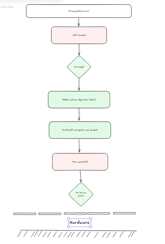
The RX path is roughly the reverse of the TX path.
For security, wfb-ng uses two layers of hierarchical encryption:
- Elliptic curve
- ChaCha20
The transmission flow works like this:
- Every second, we send a session packet containing the elliptic-curve-encrypted ChaCha20 keys.
- The actual data packets follow.
Session Packets
The "MAC" in the session packet isn't MAC-layer stuff — it's a hash used for authentication.
Data Packets

Inside wsession_data_t:
- epoch
- channel_id
- fec_type
- k
- n
- session_key
- tags
Patched WFB-ng
In real time video transmission we can't wait any packets so whatever goes wrong with any packet its simply gets dropped, now in our case our setup is the following:
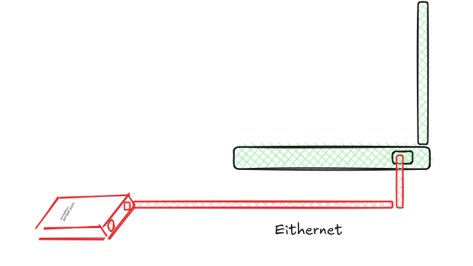
Which means that there is 2 clks in the system, the AntSDR's CPU clock and laptop CPU clock, and when you compare the speed of Ryzen 7 with a Zynq-7 thats a huge difference cause the zynq7 is a 667MHz CPU with a FPGA fabric and this is very slow.
So when we increase the datarate above 6mpbs (consider 0 FEC for simplicity) and an MTU of 1500 that means 416 packets and wfb-ng uses in its implementation sendmsg which is a scalar call and every packet calls this sendmsg function to be send from user space to kernel space, and when the data rate increases that means more packets per seconds which results in more syscalls per second, and after certain threshold the receiver FIFO is full while more packets are arriving and as we said before in real time applications we don't wait for any packets and those new packets gets dropped, one can argue that why dont we just increase the receiver FIFO but we all know that bigger FIFO means you need more time to process means you lose the original speed of the video cause of buffering effect, now a question might be asked is how didn't they thought about such a thing? now wfb-ng is designed for Raspberry Pi which for modules like the compute module 5 thats 2.4GHz of clock frequency, that wouldnt be a problem at all for such a processor but for 667MHz thats a problem and one of the best features of the linux kernel implementation or any production level piece of tech is the ability to batch calls to decrease the overhead of the indiviual sys calls but how we did it? refer to sendmmsg
In Wfb_tx we have 2 sockets, a UDP socket that listens to the Ethernet data that is comming from the laptop and another socket that is called socket packets which is the socket that takes the packets and pass them to the kernel which in its turn takes those packets to the driver that will pass it to the wifi chip and gets transmitted.
Our batch calls are implemented in the socket packet,
specifically inside the RawSocketTransmitter class -- the one that owns the socket packet bound directly to sdr0. wfb-ng has two other transmitter types, UdpTransmitter and RemoteTransmitter, used for forwarding to another process/host rather than talking to the radio directly, and those were left untouched.
Worth being precise about one thing: sendmmsg isn't a kernel patch or anything custom -- it's a completely ordinary mainline Linux syscall, in the kernel since 2.6.33 (2010) and in glibc since 2.14, the batch-send sibling of sendmsg (same family as recvmmsg on the receive side). No kernel rebuild, no driver change, nothing board-specific required -- it's userspace code in wfb_tx simply choosing to call a syscall that already exists in the stock kernel, instead of calling an older one in a loop.
We only batch the repair (FEC) fragments, never the data fragments, and the reason isn't arbitrary -- it comes down to when each kind of fragment actually exists. Data fragments arrive one at a time from ffmpeg over UDP, at whatever pace the encoder produces them, and since it's live video each one has to go out the moment it arrives -- there's nothing to batch it with, because the next one doesn't exist yet. Repair fragments are the opposite: the moment the k-th data fragment closes a block, fec_encode_simd() runs once and computes all n-k repair fragments simultaneously, from data already sitting in memory. They're all born at the same instant, so grouping their delivery into one syscall costs nothing in extra latency -- unlike batching data fragments too, which would mean holding live video packets in memory waiting for company (adds roughly k/I of latency, not worth it for a real-time link).
Mechanically: send_packet() calls start_batch() right after fec_encode_simd() returns (sets a m_batching flag), then loops over the repair fragments exactly as before -- except now inject_packet() sees the flag and, instead of calling sendmsg(), just copies the packet into an in-memory buffer and returns. Once the loop ends, end_batch() builds one array of mmsghdr (one entry per buffered fragment, each still pointing at 3 separate iovecs -- the shared radiotap header, its own ieee80211 header, its own payload) and fires a single sendmmsg() call for the whole batch. The bytes that hit the air are identical either way -- only the number of kernel crossings changes.
The syscall math, worked from a real 5 Mbps capture (879-byte average payload, k=8, n=30): input rate ≈ 711 pkts/sec, FEC block rate ≈ 88.9 blocks/sec, total injected fragments ≈ 88.9 × 30 ≈ 2,666/sec -- and before the patch, every one of those 2,666 is its own sendmsg() call. Split into data (711, unaffected by batching) and repair (1,955), batching collapses the 1,955 individual repair-fragment calls into ≈89 sendmmsg() calls (one per block), for a total of ≈800 kernel crossings/sec instead of 2,666.
One accuracy gotcha we found and fixed while wiring this into the telemetry: a batched sendmmsg() call's total time gets divided by however many fragments were in it to produce a "per-packet" latency figure for logging -- that's an amortized number, not an independently measured one, and blending it into the same latency stats as the genuinely per-packet data-fragment timings would corrupt the min/max. Fixed by giving the batched path its own distinct stat key, plus a dedicated telemetry line reporting the real, un-amortized batch call duration and fragment count.
Use Case: Throughput & Latency
The OFDM waveform used in this project targets an FPV drone video transmission system, which needs to tolerate long range and low latency.
How to calculate the latency of transmitting a single packet:
First, the constants the standard gives us to work with:
- Symbol duration = 4 µs
- L_LTF = 8 µs
- L_STF = 8 µs
- L_SIG = 4 µs
To calculate the actual throughput of the system, we divide the number of bits to transmit by the total frame duration:
T_duration = (8 x L) / T_frame
T_frame    = T_Data
T_Data     = (L_LTF + L_STF + L_SIG) + N_OFS(number of symbols) x Symbol_duration
           = 20 + N_OFS x Symbol_duration      (since L_LTF + L_STF + L_SIG = 8 + 8 + 4 = 20 µs)
N_OFS = ceil((22 + 8 x L) / N_DBPS)
We calculate the number of data bits per symbol by removing the 4 pilot subcarriers and 11 DC subcarriers, leaving 48 data subcarriers. For a modulation like QPSK, that gives us 2 bits per subcarrier — though the coding rate in use still needs to be factored in.
N_BPS  = N_Data_Subcarriers x bits_per_subcarrier
N_DBPS = N_BPS x code_rate
So, to calculate throughput (Mbps) for a packet length of 1500 bytes, a coding rate of 1/2, and QPSK modulation:
N_BPS  = 48 x 2 = 96           (subcarriers x bits per subcarrier)
N_DBPS = 96 x 1/2 = 48

N_OFS  = ceil((22 + 8 x 1500) / 48) = 250

T_Data = 20 + 250 x 4 = 1020 µs
Throughput for this system:
Throughput = (8 x 1500) / 1020 ≈ 11.7 Mbps
We'll come back to this throughput number to see how much is left over for video once we've discussed wfb-ng.
WFB-ng Overhead
Now let's calculate the effective overhead wfb-ng adds on top of raw video data — in other words, how much of what goes over the air isn't actually video.
There are two levels of overhead to account for: 1. Per-packet overhead 2. Per-burst overhead (caused by Reed-Solomon FEC)
1. Per-packet overhead
ieee80211_header   24 bytes   (4 frame ctrl + 6 dst MAC + 6 src MAC + 6 BSSID + 2 seq)
wblock_hdr_t        9 bytes
wpacket_hdr_t       3 bytes
AEAD auth tag      16 bytes
------------------------
total overhead     52 bytes

user data        1500 bytes
------------------------
total on-air     1552 bytes per packet
2. Per-burst overhead (Reed-Solomon)
The real wfb-ng throughput overhead comes from the Reed-Solomon FEC layer. Let's take an example: a Reed-Solomon block with k = 8 and n = 12.
What do these parameters mean? For every k data packets, the encoder produces n − k parity packets, giving n packets on the air in total.
So for a burst of k = 8 packets, using the 1552-byte on-air packet size from above:
Data payload   (k = 8 packets):     1552 x 8 = 12,416 bytes
Parity payload (n - k = 4 packets): 1552 x 4 =  6,208 bytes
------------------------------------------------------------
Total on-air   (n = 12 packets):    12,416 + 6,208 = 18,624 bytes
FEC overhead = (n − k) / k = 4 / 8 = 50%
Useful user data in this burst: 1500 x 8 = 12,000 bytes

Combined efficiency (useful user data ÷ total on-air):
12,000 / 18,624 ≈ 64.4% user data
                  35.6% overhead
So, to summarize, wfb-ng overhead comes down to two layers: 1. PHY-level overhead, per packet — the coding rate paired with whichever modulation is in use (e.g., QAM16 at a 1/2 coding rate). 2. Overhead per burst of packets — the Reed-Solomon parity shown above.
Producing the Same Project Again
Now let's discuss how to reproduce the project. We use the AntSDR board, which has support for openwifi.
Board Characteristics
The AntSDR is quite powerful — it has: 1. Zynq-7020 2. AD9361
(TODO — power consumption, resource utilization, and latency figures still need to be filled in here.)
Since openwifi runs on the Zynq-7's FPGA fabric, and openwifi is standard-compliant with 802.11a/g/n, any WiFi dongle will work with it.
Choosing a WiFi Dongle
For our setup, we tested openwifi with two WiFi chipsets: 1. RTL8821CU 2. RTL8822BU
To support packet injection, the WiFi dongle needs a chipset with mature packet-injection support built into the hardware and its corresponding driver. A curated list of such adapters is available here: USB-WiFi: Recommended Adapters for Kali Linux
There's also the Atheros AR9271.
We used a cheap $4 WiFi dongle for initial, simple indoor testing, based on the RTL8812CU: github.com/lwfinger/rtw88
You'll need to enable this driver's patch to get the chipset working in monitor mode with packet injection — and what is monitor mode, you might ask?
Monitor mode: a WiFi dongle mode that lets you monitor the link around you — it can detect any packet in the air, whether it's on your network or someone else's.
Building and Running wfb-ng
Clone wfb-ng and build it:
git clone https://github.com/svpcom/wfb-ng
make
Before running make: install libsodium and libpcap first. You'll likely hit errors building the test suite — if you actually need the test suite, install whichever library the error names; otherwise, just skip the error and move on.
Now you can generate keys by running:
./wfb_keygen
This gives you the GS key and the drone key. Copy (or rsync) drone.key over to any unit you want to use for receiving video.
On the receiver, use GStreamer or ffplay to display the video.
Transmitter Setup (AntSDR)
Install wfb-ng on the AntSDR — either cross-compile wfb-ng for ARM, specifically the ARM Cortex-A9 core (more on a limitation of this core in the Patched WFB-ng section).
After that, make sure to run the commands from the "Operating the PHY" section:
~/openwifi/wgd.sh
~/openwifi/monitor sdr0 channel
~/openwifi/sdrctl dev sdr0 set reg xpu 11 48
If you want to transmit on a frequency other than the ones listed by:
iwlist freq
use:
~/openwifi/sdrctl dev sdr0 set reg ef 5 freq # this is for TX only — for RX, use 1 instead of 5
After all of this, you can start transmitting:
- Connect the AntSDR to your laptop via Ethernet and start the ffmpeg or GStreamer command.
- Make sure the MTU / RTP cap / RTP size option is set to 1400.
- Start wfb_tx (make sure you have drone.key):
./wfb_tx -K drone.key -k 8 -n 12 -u port -p 0 -i 0 \
  -B 20 -S 0 -L 0 -G long -M 7 \
  -F 1000 -Q -J 10 -E 2000 -f data sdr0
Receiver Setup
Start wfb_rx on the receiving machine:
~/wfb-ng/wfb_rx -K ~/wfb-ng/gs.key -p 0 -i 0 -c 127.0.0.1 -u port wifi-dongle-interface-name